1 How to use the Cubeling app
1.1 Basic actions with cubes
When you open the app, you will see a split screen: a 3D view on the left and the building plan on the right.
Fig. 1.1: App launch screen
The app uses two basic actions:
Add cube
To add a cube, tap on one of the dark or light gray squares. You can, of course, also place a cube on top of another one, and another one, and so on – simply tap on the respective cube again and again.
Remove cube
Touch and hold a cube to remove it.
This explanation can also be found in the app by tapping on the i at the bottom left. You can add and remove cubes in both the 3D view and in the building plan mode1. When you change something in one view, the same modification is immediately and automatically adopted in the other view.
The trash can button at the bottom center allows you to delete the entire connected cube structure.
Didactic note
Naturally, the actions add cube and remove cube also exist when working with real cubes. In the app, however, there are relatively strong constraints for this: You do not have to first pick up a cube, you do not have to align it perfectly to the checkerboard pattern, you do not have to let it go – the only thing you have to do is click on the square where you want it. On the one hand, you lose out on a range of real, haptic experiences (which goes to show that you should not forgo real cubes entirely). On the other hand, this gives students with fine motor control limitations the opportunity to solve more complex tasks with the help of cube structures, which they might not be able to do with real objects.
1.2 Global settings
In the main settings app on your device2 you can set your preferences for the app.
Fig. 1.2: App settings
You can decide whether the colored coordinate axes should be displayed and if they should be labeled with numbers.
You can also change the size of the board – ranging between 3x3 and 10x10.
Additionally, you can choose between wooden cubes, stackable cubes, and magic cubes. In addition to slight visual differences, there is also a difference in the building behaviour of the cubes.
- Wooden cubes can only be stacked on top of each other, i.e., a cube always needs to lie either on top of another cube or directly on the board.
- Stackable cubes, on the contrary, can also be attached laterally. This plays a role when removing cubes as well: Wooden cubes can only be removed from top to bottom, whereas stacking cubes can be removed freely, as long as no cubes are left “floating” in the air.
- Magic cubes can float. The construction is the same as with wooden cubes, but you can remove magic cubes freely, so that it is possible to have floating cubes remain.
You can also decide whether loops and variables are possible in the code view. You can find more on this in section 1.5.
1.3 Modify and switch views
1.3.1 Rotate and zoom into connected cube structure
Rotate the 3D view using one finger and zoom in or out with two. This gives you the ability to move around the cube structure (view the structure from all sides). It is also possible to view the structure from below.
1.3.2 Shadow walls and transparency
By clicking on the three dots at the bottom left, you can build shadow walls and change the transparency of the cubes.
Fig. 1.3: Configuring the shadow walls
1.3.3 Outline
Via the same three dots, you can also set your ability to see the outline of the built cube structure. You can choose between the regular cubes (sun), the disappearance of contours (cloud) or completely blacked out cubes (moon).
Fig. 1.4: Outline of connected cube structure
1.3.4 Further views
You can use the toggle buttons at the bottom to switch between views. On the left you have the familiar 3D view and the building plan. On the right, in addition to the building plan, you can choose between the multiview orthographic projection, the oblique view in cavalier perspective, the isometric view, and (for wooden cubes) a code view. Again, if you change something in one view, you will immediately see the change in the others as well.
However, cubes cannot be added when you are in the multiview orthographic projection or one of the oblique views – this is only possible in the 3D view and (for wooden cubes) in the building plan as well as the code view.
It is possible to completely hide the left or right view via the toggles at the respective corners.
Hiding a view can be useful if, for example, you provide a building plan and have your students build the connected cube structure using real cubes. Then, they can use the app to check their creations.
1.3.4.1 Multiview orthographic projection
If you choose the multiview orthographic projection, a red bar will appear in both individual views, with a small cube at the end on one side and a small sphere on the other. This bar acts a way to orient yourself should the 3D view ever be wildly rotated. This is especially helpful if you have switched off the blue and green axes in the global settings.

Fig. 1.5: Multiview orthographic projection
If you are in the multiview orthographic projection and zoom out with two fingers, a third pane – the side view – will appear.
1.3.5 Oblique projections
The two oblique views also display the cube structure. In the isometric view, a small red stick can been seen between the squares (2|2) and (3|3). This can aid in the interpretation of the representations.
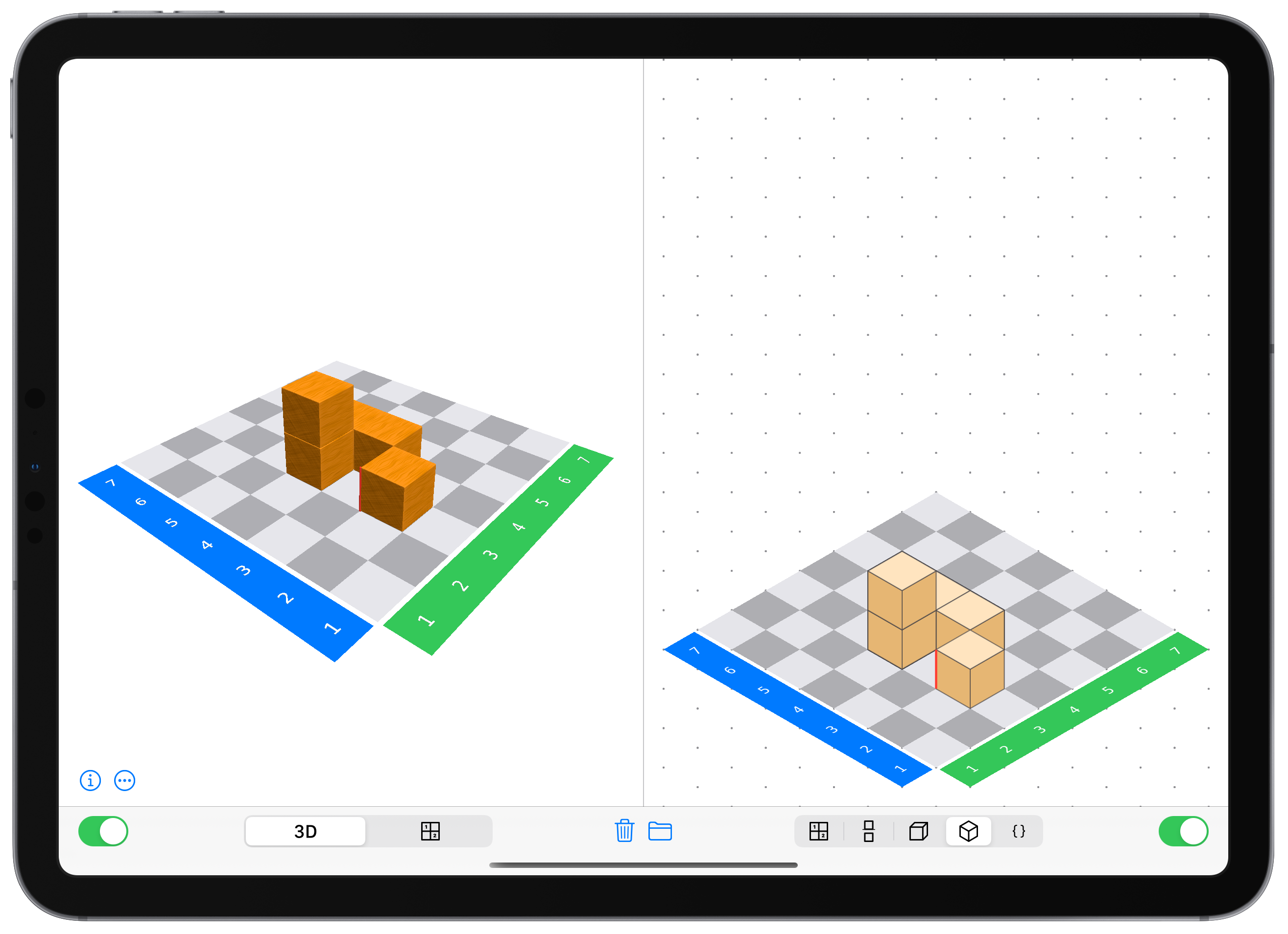
Fig. 1.6: Isometric view
1.3.6 Code-view
This function is only available when using wooden cubes and is not a feature available on iPhones.
There is also a code view, which documents the building process of the cube structure. Here, once again, a variety of actions are possible, which will be discussed in more detail in chapter 1.5.
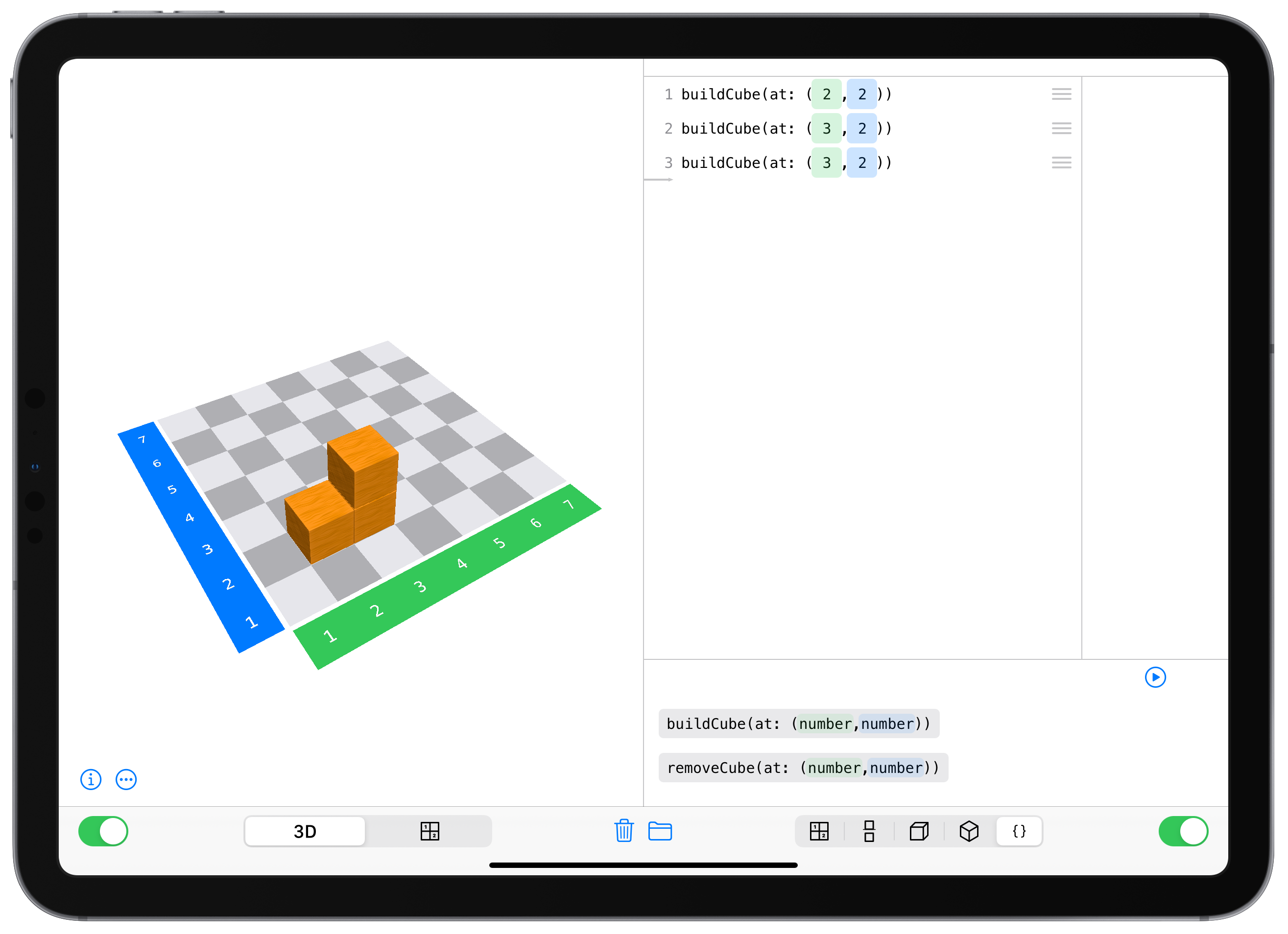
Fig. 1.7: Code view
1.4 Export and import
If you click on the folder button in the middle (next to the trash can), it is possible to export either the entire connected cube structure or only individual views, as well as open a previously saved cube structure.
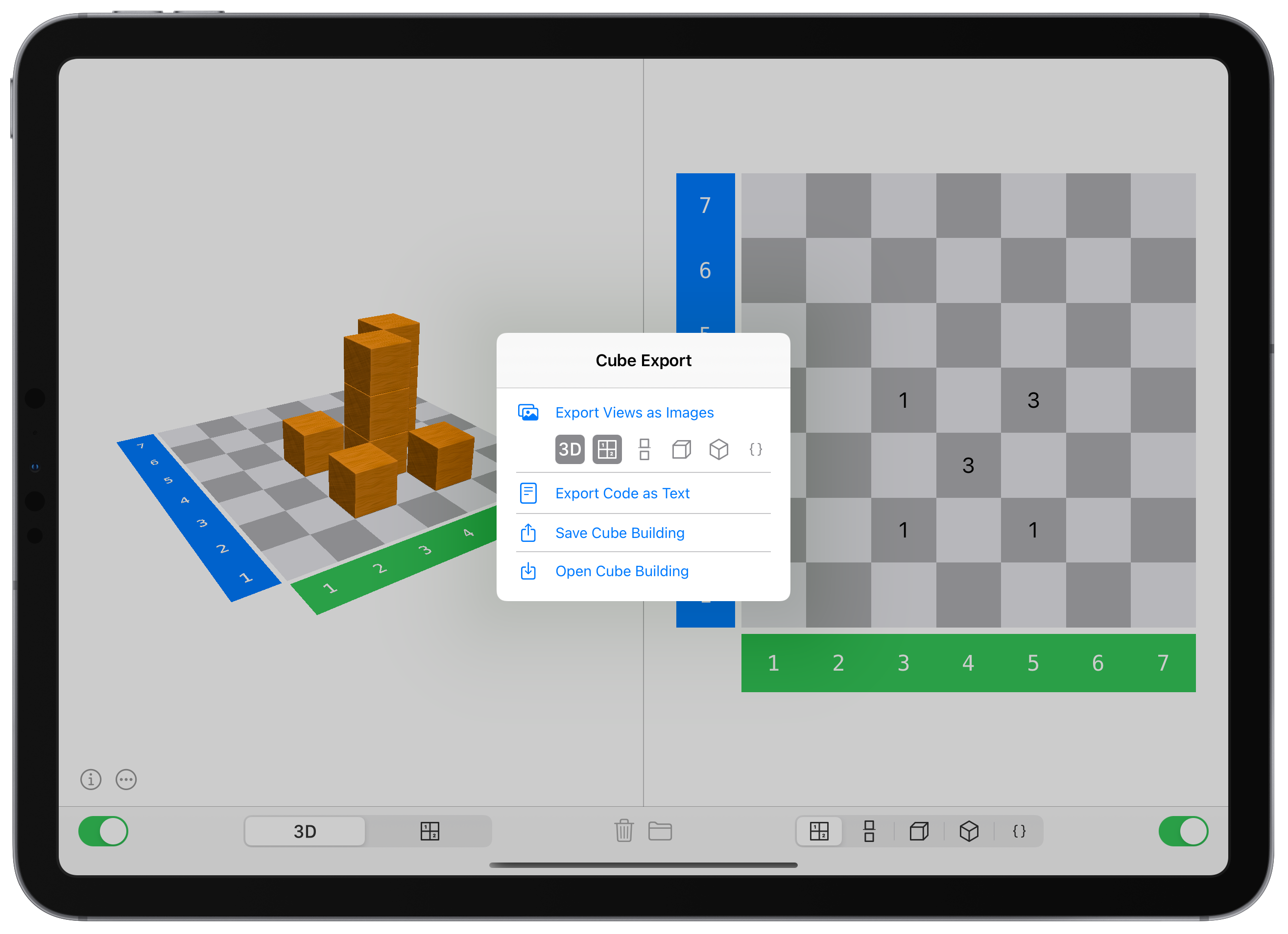
Fig. 1.8: Export and import
1.4.1 Export views as images
Select which of the six views you want to export. Then you can save or share them as png-files.
1.4.2 Export code as text
This function is only available when using wooden cubes and is not a feature available on iPhones.
The code documenting the construction process of the cube structure can be saved or shared as a txt-file.
1.4.3 Save connected cube structure
Click here to save or share the entire cube structure, including all the settings that were used during its construction.
The exported file is a cubl file, a custom file format for the Cubeling app.
If you share a cube structure (via AirDrop or email, for example) with your students who also have the Cubeling app, they can open the cube structure on their devices.
1.4.4 Open connected cube structure
If a cubl file is saved on the device, you can click here to open it.
It is also possible to open files that were created with older version of the Cubeling app (up to version 6.0, these are then cubeling-files), but it might be that not all settings are transferred.
1.5 How to work with the code view
In the code view, the first thing that is documented is which cubes are added or removed in either the 3D view or building plan.
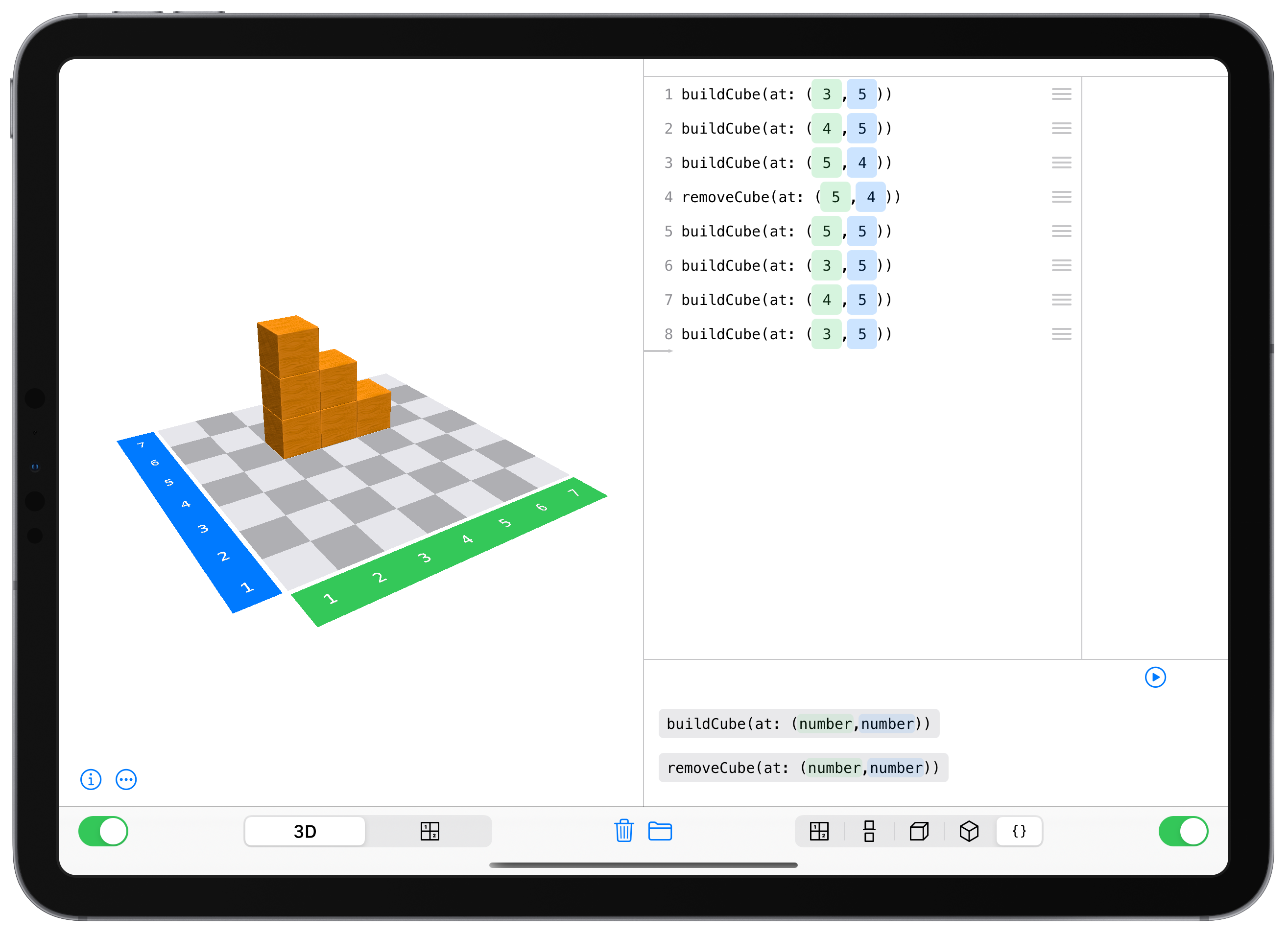
Fig. 1.9: Coding with Cubeling
1.5.1 Add a line of code
It is possible for users to manually add commands. For this, the corresponding buttons at the bottom of the code view need to be selected:
buildCube(at: (number,number))inserts a cube at the specified coordinates.removeCube(at: (number,number))removes a cube (should it exist).
Provided that loops are allowed in the global setting, the following are also possible:
do counting number times {…}creates a repetition so that the command in the curly brackets is executed the specified number of times.
If variables are also allowed in the global settings, further commands exist:
position = (number,number)creates a variable, for examplepositionA.- Change a variable in one direction with
change(position, by: (number,number)), for examplechange(positionA, by: (1,0)). - With
buildCube(at: position))andremoveCube(at: position), you can now use the positions to add or remove cubes there.
You can change where a line of code is inserted via the gray arrow on the left edge of the code view.
Fig. 1.10: Change build location
1.5.2 Remove a line of code
To remove a line of code, swipe it left. A trash can with red backdrop will appear, which you can use to delete that line.
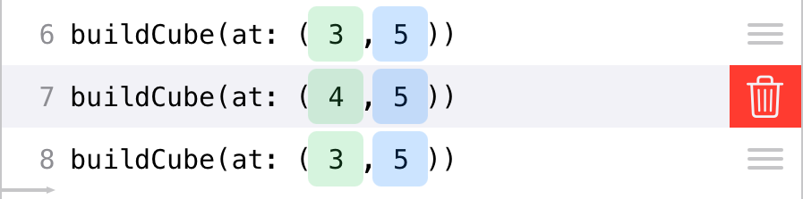
Fig. 1.11: Delete line of code
1.5.3 Move a line of code
Rearrange code elements via the three lines at the right edge of the code.
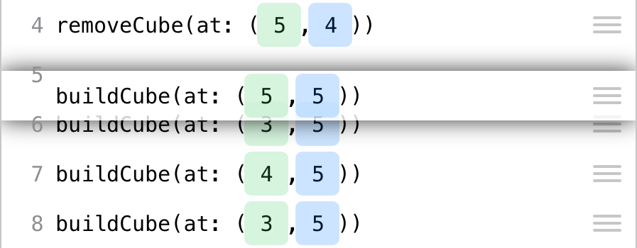
Fig. 1.12: Rearrange lines of code
At this point, it could be interesting to see how changing the order of lines of code changes the resulting cube structure. As long as only
buildCubecommands are used, this does not produce very exciting results. However, as soon as loops or variables are included, or theremoveCubecommand is used, this can lead to interesting discoveries.
You can also drag individual lines of code into or out of existing loops.
1.5.4 Changing numbers
There are two ways to change the numbers, like those used to describe the coordinates, in your code. In both cases, you first have to tap on the number itself.
- You can now use the number pad to enter the numbers, just like on a computer keyboard. The ±-key allows you to quickly turn a number into its opposite number.
- You can use the arrow keys to increase or decrease the numbers step by step.
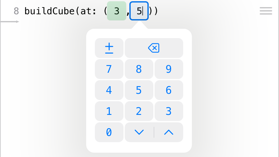
Fig. 1.13: Change numbers
1.5.5 Code tracing
Clicking on the play button below the code starts the code tracing. Using the arrows, the code can now be executed one step at a time.
In this way, it is possible to retrace the individual construction steps. This is particularly interesting if loops were used.
If a loop is being traced, the number of the current pass is displayed. Accordingly, at the end of the loop, it is decided whether it starts again or if it continues to the next line of code.
Moreover, it is possible to have the current value of a position displayed. This is relevant if the value of a position changes within a loop and this change is to be understood.
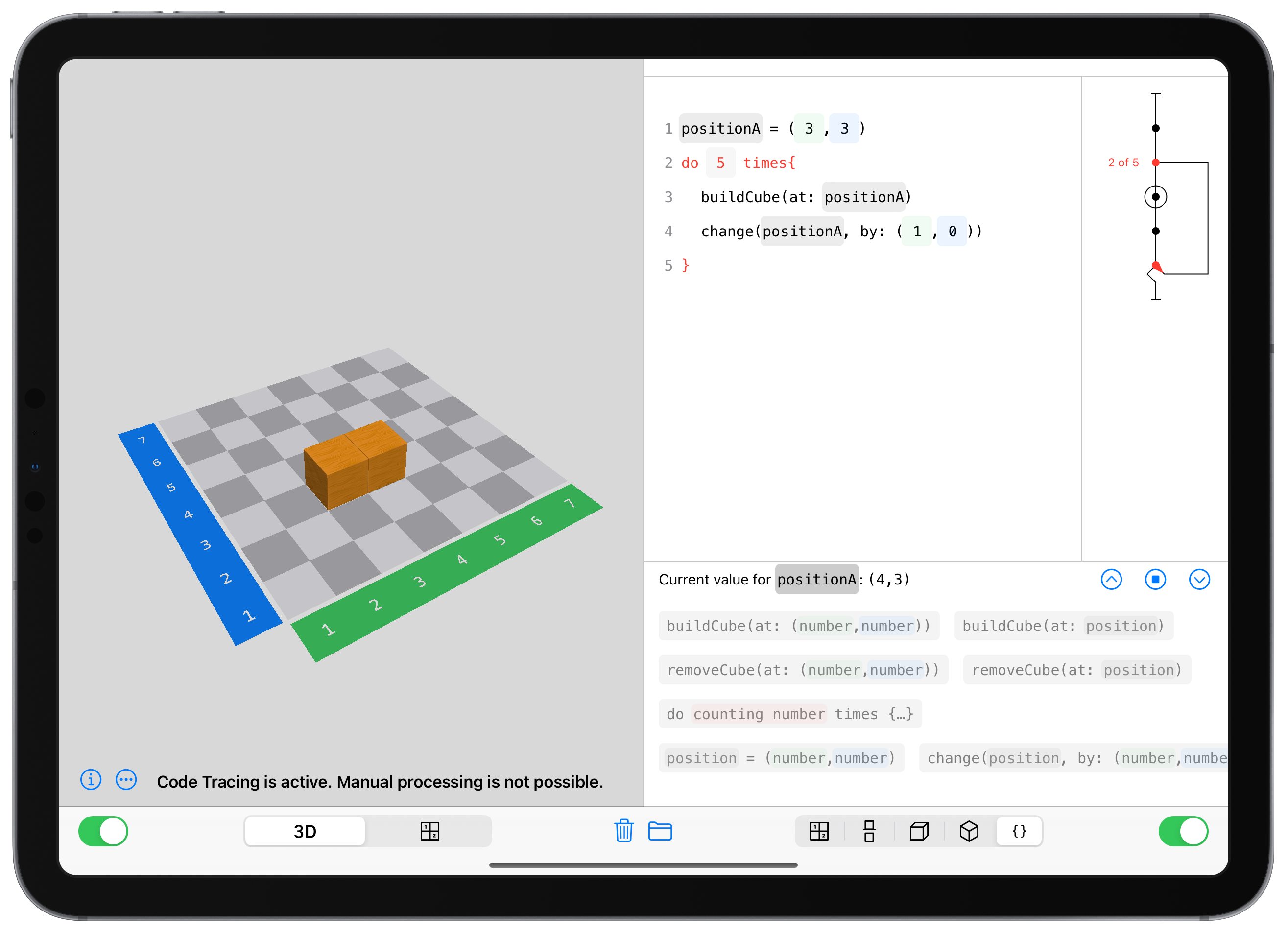
Fig. 1.14: Code tracing
In the building plan view, you can only add or remove cubes if you have selected wooden cubes, otherwise the uniqueness of the structure could not be guaranteed↩︎
This is the app with the gray gear symbol. Open it and scroll down until you find the Cubeling app. If you are using the Cubeling app on a Mac, you can open the settings in the menu bar by clicking Cubeling → Preferences.↩︎